

Top Types of Expulsion Fuses for Global Buyers
Expulsion Fuses protect overhead distribution systems by interrupting fault current and helping isolate damaged sections. Their familiar drop-out action also gives crews a visible indication that a fuse has operated. Yet choosing one is not a simple catalog exercise. Voltage, available fault current, load characteristics, mounting conditions, and coordination with upstream devices all matter.
This guide compares common options, including open and enclosed cutouts, dropout designs, and fuse links with different operating characteristics. It also considers where each type may fit, what buyers should verify, and which product details deserve close attention. Power-distribution author Thomas A. Short’s published work discusses protection as part of the wider distribution system. A fair paraphrase of that principle is: “Choose protection for the system, not just the component.” This is a paraphrase, not a direct quotation.
A fuse that looks right on paper can still be poorly matched to a real feeder. Check rated voltage, interrupting capacity, insulation requirements, and compatibility with the specified cutout. Ask suppliers for current technical data and confirm that claims match recognized standards and the project specification. Small details matter. So does installation context. Global buyers may face different operating environments and procurement requirements, and product labels alone do not settle every question. This overview offers a practical starting point—not a substitute for engineering review. Some comparisons will remain imperfect, because product ranges and local network conditions differ. That uncertainty is worth acknowledging.
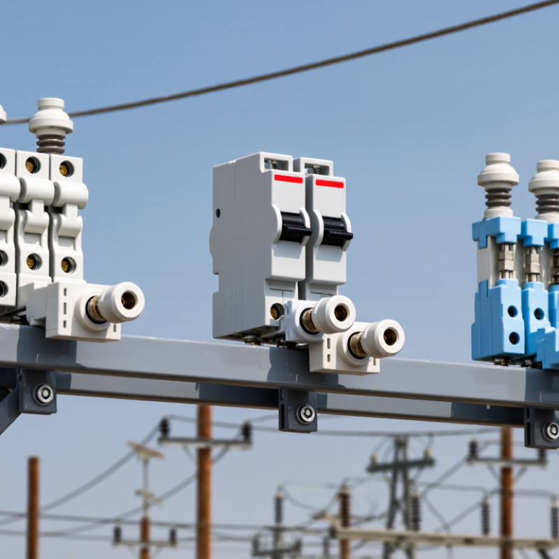
What Expulsion Fuses Are and How They Interrupt Faults
An expulsion fuse is a single-phase protective device commonly used on overhead distribution lines and transformers. When excessive current melts its fuse link, an arc forms inside the fuse tube. Heat and arc energy generate gases from the tube lining, which drive hot gases outward and help stretch and cool the arc. At an alternating-current zero crossing, the arc can extinguish. The sequence is physical. Its success depends on the fuse’s rated voltage, fault current, and installation conditions.
IEEE C37.41 sets design and test requirements for high-voltage fuse cutouts and fuse links; it does not promise one clearing time for every fault. That distinction matters. The U.S. Energy Information Administration reported an average of 5.5 hours of electricity interruptions per customer in 2022, including major events, in its Electric Power Annual reliability data. This figure describes outages overall, not fuse performance. A correctly selected fuse can isolate certain faults, but it cannot prevent every interruption.
For buyers, compare voltage and current ratings, minimum and maximum interrupting capacity, and time-current curves against the protected equipment and available fault level. Check the tube material, creepage distance, and fit with the intended cutout assembly. Real installations are less tidy than catalogue tables. Moisture, contamination, and incorrect link selection can change performance, so local system data and qualified engineering review still matter.
Key Components and Operating Sequence of an Expulsion Fuse
An expulsion fuse has a small set of parts, each with a distinct job. The fuse link carries normal current until excess current melts it. A surrounding fuse tube contains an arc-quenching liner, often made from gas-generating material. Contacts and a hinged drop-out assembly hold the tube in place. A clear marker matters.
During a fault, the link melts and an arc forms inside the tube. Heat from the arc causes the liner to release gas, which helps cool and lengthen the arc. At an alternating-current zero crossing, the arc can be extinguished. The tube then swings down, giving crews a visible indication of operation. The sequence is quick, but not always tidy: weather, contamination, and incorrect coordination can affect performance.
IEC 60282-2:2008 covers expulsion fuses for AC systems above 1 kV, providing a useful application boundary. IEEE C37.41-2016 specifies design and test requirements for high-voltage fuses. These references support checking rated voltage, interrupting capability, and test performance against the installation’s conditions. A rating alone is not enough. Load current and available fault current must also be considered.
Major Expulsion Fuse Types by Design and Mounting
Expulsion fuses are classified by how they interrupt current and how they attach to equipment. In an open-link dropout cutout, the fuse link sits inside a hinged tube. When it operates, the tube drops open, leaving a visible gap on the pole. That clear indication is useful during inspections. It is not a substitute for checking the equipment safely.
Enclosed expulsion fuses contain the arc within a tube or housing. Some use a gas-generating lining; boric-acid designs use material that helps extinguish the arc. These forms suit different voltage, current, and fault-duty requirements, so their ratings are not interchangeable. Details matter. The categories can overlap in product descriptions, which makes specification sheets worth reading carefully.
Mounting also shapes the choice. Pole-mounted cutouts commonly attach to crossarms or brackets on outdoor distribution lines. Other expulsion fuse assemblies fit designated outdoor equipment, such as transformers or capacitor installations. Their mounting hardware, clearances, and vent direction must match the equipment design. A fuse that vents into a nearby obstruction may not perform as intended. Indoor use should never be assumed; confirm the manufacturer’s stated application and installation conditions. In practice, the right type depends on both its electrical duty and the space around its mounting point.
| Fuse Type or Arrangement | Design and Operating Principle | Typical Mounting | Common Applications | Key Selection Considerations |
|---|---|---|---|---|
| Dropout fuse cutout | The fuse link is housed in a hinged fuse tube. When the link operates, the tube drops open, providing a visible indication that the fuse has blown and helping isolate the circuit. | Usually mounted outdoors on a utility pole, crossarm, or transformer structure. Single-phase units are commonly installed individually; three units may be used for a three-phase circuit. | Overhead distribution feeders, transformer primary protection, and taps or laterals. | Check rated voltage, continuous current, interrupting capability, insulation level, fuse-link compatibility, and the required coordination with upstream and downstream protection. |
| Non-dropout expulsion fuse | The fuse element operates within an expulsion tube, but the assembly is designed not to drop open after operation. Fault interruption still relies on the expulsion-fuse design and its specified operating conditions. | Mounted on a fixed outdoor support or equipment structure, following the manufacturer's specified orientation and clearances. | Installations where a falling fuse tube is not desired or where the equipment arrangement calls for a fixed assembly. | Confirm the exact product construction and indication method; a non-dropout unit may not provide the same visible open-gap indication as a dropout cutout. |
| Open-type expulsion fuse | The interrupting tube is exposed to the surrounding air. As the fuse link operates, gases generated inside the tube help extinguish the arc. Many overhead dropout cutouts use this general arrangement. | Typically mounted outdoors on poles, crossarms, or other open-air distribution structures. | Overhead distribution systems where the equipment can be installed with suitable phase spacing and exhaust clearances. | Provide the clearances and installation environment required by the applicable standards and manufacturer. Expulsion gases and noise during interruption must be considered. |
| Enclosed expulsion fuse | The expulsion fuse is housed within an enclosure designed for the specific fuse assembly. The enclosure does not eliminate the need to follow the product's requirements for gas discharge, ventilation, and fault interruption. | Installed in equipment or a structure specifically designed and approved for that fuse type; mounting may be indoors or outdoors only where the equipment rating permits. | Selected distribution or equipment applications that require an enclosed fuse arrangement compatible with the installation. | Verify enclosure compatibility, ventilation and exhaust provisions, accessibility, environmental rating, and the fuse's tested interrupting rating. Do not substitute an open-type fuse in an enclosure without approval. |
| Single-pole, individually mounted arrangement | One fuse assembly protects one phase. A single-pole arrangement describes the installation configuration rather than a different arc-extinguishing mechanism. | Mounted separately on a pole, crossarm, transformer bracket, or equipment support. | Single-phase circuits and individual phase protection on overhead distribution systems. | Confirm phase-to-ground insulation requirements, structural loading, safe operating access, and coordination with other protective devices. |
| Three-pole or three-unit arrangement | Three single-pole fuse units are installed to protect a three-phase circuit. They may operate independently unless the system includes a separate mechanism designed to operate them together. | Mounted as three separate units or on a common support, with spacing and orientation set by the equipment design. | Three-phase overhead feeders, transformer connections, and other distribution equipment. | Consider phase coordination, the consequences of single-phasing, required clearances, and whether the protection scheme calls for independent or linked operation. |
| Buyer note: Expulsion-fuse ratings and mounting requirements vary by product and application. Select equipment using the system voltage, load current, available fault current, insulation and environmental requirements, fuse-link coordination, and the applicable electrical standards. | ||||
How to Match Fuse Types to Voltage and Application
Top Types of Expulsion Fuses for Global Buyers
How to Match Fuse Types to Voltage and Application
Matching an expulsion fuse starts with the system voltage, not the equipment’s appearance. Check the network’s voltage class and the fuse’s rated maximum voltage. Then confirm its interrupting capacity can handle the available fault current at the installation point. These checks matter more than choosing a familiar-looking cutout.
For outdoor distribution transformers and overhead lines, a dropout cutout fuse is common. Its hinged tube falls open after operation, making the interruption visible from the ground. Enclosed expulsion fuses may suit installations needing a more contained design. Some medium-voltage applications use boric-acid power fuses, which can interrupt higher fault currents; verify their ratings and intended duty before selection. Match the fuse link’s current rating to the protected equipment, expected load, and coordination plan. A transformer’s inrush current also matters, or nuisance operations may follow.
Details count. Check mounting style, altitude, temperature, and the manufacturer’s published ratings. In practice, selection is not always tidy: system data can be incomplete, and a fuse that fits mechanically may still be unsuitable electrically. Have a qualified protection professional review the application and coordination study before installation.
Global Buyer Checks for Ratings, Standards, and Compatibility
Expulsion fuses are commonly supplied as dropout cutouts for overhead distribution, with porcelain or polymer housings. Buyers should compare more than housing material. Check rated voltage, continuous current, interrupting capacity, and insulation level against the actual system data. A fuse must also withstand the available fault current at its installation point. Do not assume that similar-looking cutouts share the same ratings. Small differences matter.
Tips: Request the current datasheet and applicable test-standard references. IEC and IEEE documents may use different requirements, and editions can change. Confirm the fuse-link type and time-current curve, mounting dimensions, terminal arrangement, and operating mechanism. Then check these details against the transformer, conductor, and protection scheme. Keep the records. They help prevent ordering errors.
Compatibility deserves a site-level review. Consider system voltage, grounding method, expected load, and coordination with upstream and downstream protection. Ask the supplier to clarify any rating that is missing or stated ambiguously. A tidy comparison table helps, though it cannot replace engineering review. In practice, teams sometimes overlook clearance or mounting constraints until installation day. Measure the existing support and verify drawings before purchase. If site conditions are uncertain, pause and confirm them rather than guessing.
